Lithium Battery Management Systems (BMS)
A Battery Management System (BMS) is an intelligent component of a battery pack responsible for advanced monitoring and management. It is the brain behind the battery and plays a critical role in its levels of safety, performance, charge rates, and longevity.
Battery management system (BMS) is technology dedicated to the oversight of a battery pack, which is an assembly of battery cells, electrically organized in a row x column matrix configuration to enable delivery of targeted range of voltage and current for a duration of time against expected load scenarios.
Our BMS is designed to be a long-term solution for our customers with the highest level of safety in mind. Advanced algorithms and electronics ensure high precision measurements:
Functionally safe
Fast and efficient balancing
Shortened charging time
Improved range per charge
Maximum battery life
The oversight that a BMS provides usually includes:
Monitoring the battery
Providing battery protection
Estimating the battery’s operational state
Continually optimizing battery performance
Reporting operational status to external devices
How do battery management systems work?
Battery management systems do not have a fixed or unique set of criteria that must be adopted. The technology design scope and implemented features generally correlate with:
The costs, complexity, and size of the battery pack
Application of the battery and any safety, lifespan, and warranty concerns
Certification requirements from various government regulations where costs and penalties are paramount if inadequate functional safety measures are in place
There are many BMS design features, with battery pack protection management and capacity management being two essential features. We’ll discuss how these two features work here. Battery pack protection management has two key arenas: electrical protection, which implies not allowing the battery to be damaged via usage outside its SOA, and thermal protection, which involves passive and/or active temperature control to maintain or bring the pack into its SOA.
Electrical Management Protection: Current
Monitoring battery pack current and cell or module voltages is the road to electrical protection. The electrical SOA of any battery cell is bound by current and voltage. Figure 1 illustrates a typical lithium-ion cell SOA, and a well-designed BMS will protect the pack by preventing operation outside the manufacturer’s cell ratings. In many cases, further derating may be applied to reside within the SOA safe zone in the interest of promoting further battery lifespan.
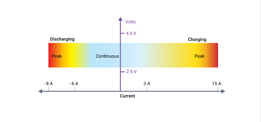
Lithium-ion cells have different current limits for charging than for discharging, and both modes can handle higher peak currents, albeit for short time periods. Battery cell manufacturers usually specify maximum continuous charging and discharging current limits, along with peak charging and discharging current limits. A BMS providing current protection will certainly apply a maximum continuous current.
However, this may be preceded to account for a sudden change of load conditions; for example, an electric vehicle’s abrupt acceleration. A BMS may incorporate peak current monitoring by integrating the current and after delta time, deciding to either reduce the available current or to interrupt the pack current altogether. This allows the BMS to possess nearly instantaneous sensitivity to extreme current peaks, such as a short-circuit condition that has not caught the attention of any resident fuses, but also be forgiving to high peak demands, as long as they are not excessive for too long.
BMS SYSTEM OVERVIEW
The EV Power LiFePO4 BMS consists of two parts:
1) Battery Control Unit (BCU) – one BCU per battery pack, monitors the battery voltage and the cell module loop and takes action to prevent charging or discharging if there is a fault.
2) Cell Modules – one per cell which can work as passive shunt balancers and link together via our proprietary one wire NC Loop to provide a signal to the BCU if one or more cells is outside its safe voltage range.
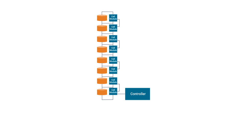
CELL MODULES
The heart of the EV Power system is the analog passive cell balancer/monitor module. Simple and elegant. There is one cell module for each cell in a battery. The cell modules perform the function of balancing and monitoring the cells. Each cell module has a green LED to indicate OK status (when on) and a red LED to indicate when the module is “balancing” the cell.
Aimeno developed its unique one wire system that connects each cell module to the next. This provides two ends that interface back to a battery control unit which controls charge and discharge.
Cell Module Features:
Epoxy Encapsulated to prevent moisture and dust interference. Also keeps out bugs, dropped spanners, loose cables, nuts and fingers!
Gold plated cell terminal connectors for perfect connection and professional looks.
One wire link between cell modules. We invented the system.
Low profile, does not even protrude above terminal bolts.
Up to 2A shunt current capacity (CBM400).
No heat buildup when regulating, no bulky hot resistors.
Small footprint the actual circuit is the size of a postage stamp! It does not interfere with mounting hardware.
Low power consumption 3+ years to drain a 100Ah idle cell.
Reverse polarity protected.
Simple to install and easy to understand.
Sizes suitable for most prismatic LiFePO4 cells.
Electrical Management Protection: Voltage
Figure 2 shows that a lithium-ion cell must operate within a certain voltage range. These SOA boundaries will ultimately be determined by the intrinsic chemistry of the selected lithium-ion cell and the temperature of the cells at any given time. Moreover, since any battery pack experiences a significant amount of current cycling, discharging due to load demands and charging from a variety of energy sources, these SOA voltage limits are usually further constrained to optimize battery lifespan. The BMS must know what these limits are and will command decisions based upon the proximity to these thresholds.
For example, when approaching the high voltage limit, a BMS may request a gradual reduction of charging current, or may request the charging current be terminated altogether if the limit is reached. However, this limit is usually accompanied by additional intrinsic voltage hysteresis considerations to prevent control chatter about the shutdown threshold. On the other hand, when approaching the low voltage limit, a BMS will request that key active offending loads reduce their current demands. In the case of an electric vehicle, this may be carried out by reducing the allowed torque available to the traction motor. Of course, the BMS must make safety considerations for the driver the highest priority while protecting the battery pack to prevent permanent damage.
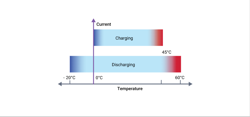
Thermal Management Protection: Temperature
At face value, it may appear that lithium-ion cells have a wide temperature operating range, but overall battery capacity diminishes at low temperatures because chemical reaction rates slow down remarkably. With respect to capability at low temperatures, they do perform much better than lead-acid or NiMh batteries; however, temperature management is prudently essential since charging below 0 °C (32 °F) is physically problematic. The phenomenon of plating of metallic lithium can occur on the anode during sub-freezing charging. This is permanent damage and not only results in reduced capacity, but cells are more vulnerable to failure if subjected to vibration or other stressful conditions. A BMS can control the temperature of the battery pack through heating and cooling.
Realized thermal management is entirely dependent upon the size and cost of the battery pack and performance objectives, design criteria of the BMS, and product unit, which may include consideration of targeted geographic region (e.g. Alaska versus Hawaii). Regardless of the heater type, it is generally more effective to draw energy from an external AC power source, or an alternative resident battery purposed to operate the heater when needed. However, if the electric heater has a modest current draw, energy from the primary battery pack can be siphoned to heat itself. If a thermal hydraulic system is implemented, then an electric heater is used to heat the coolant which is pumped and distributed throughout the pack assembly.
Types of battery management systems
Battery management systems range from simple to complex and can embrace a wide range of different technologies to achieve their prime directive to “take care of the battery.” However, these systems can be categorized based upon their topology, which relates to how they are installed and operate upon the cells or modules across the battery pack.
Centralized BMS Architecture
Has one central BMS in the battery pack assembly. All the battery packages are connected to the central BMS directly. The structure of a centralized BMS is shown in Figure 6. The centralized BMS has some advantages. It is more compact, and it tends to be the most economical since there is only one BMS. However, there are disadvantages of a centralized BMS. Since all the batteries are connected to the BMS directly, the BMS needs a lot of ports to connect with all the battery packages. This translates to lots of wires, cabling, connectors, etc. in large battery packs, which complicates both troubleshooting and maintenance.

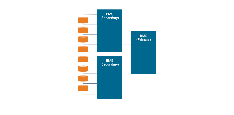
Modular BMS Topology
Similar to a centralized implementation, the BMS is divided into several duplicated modules, each with a dedicated bundle of wires and connections to an adjacent assigned portion of a battery stack. See Figure 7. In some cases, these BMS submodules may reside under a primary BMS module oversight whose function is to monitor the status of the submodules and communicate with peripheral equipment. Thanks to the duplicated modularity, troubleshooting and maintenance is easier, and extension to larger battery packs is straightforward. The downside is overall costs are slightly higher, and there may be duplicated unused functionality depending on the application.

Primary/Subordinate BMS
Conceptually similar to the modular topology, however, in this case, the slaves are more restricted to just relaying measurement information, and the master is dedicated to computation and control, as well as external communication. So, while like the modular types, the costs may be lower since the functionality of the slaves tends to be simpler, with likely less overhead and fewer unused features.
Distributed BMS Architecture
Considerably different from the other topologies, where the electronic hardware and software are encapsulated in modules that interface to the cells via bundles of attached wiring. A distributed BMS incorporates all the electronic hardware on a control board placed directly on the cell or module that is being monitored. This alleviates the bulk of the cabling to a few sensor wires and communication wires between adjacent BMS modules. Consequently, each BMS is more self-contained, and handles computations and communications as required. However, despite this apparent simplicity, this integrated form does make troubleshooting and maintenance potentially problematic, as it resides deep inside a shield module assembly. Costs also tend to be higher as there are more BMSs in the overall battery pack structure.
The benefits of battery management systems
An entire battery energy storage system, often referred to as BESS, could be made up of tens, hundreds, or even thousands of lithium-ion cells strategically packed together, depending on the application. These systems may have a voltage rating of less than 100V, but could be as high as 800V, with pack supply currents ranging as high as 300A or more. Any mismanagement of a high voltage pack could trigger a life-threatening, catastrophic disaster. Consequently, therefore BMSs are absolutely critical to ensure safe operation. The benefits of BMSs can be summarized as follows.
Functional Safety. Hands down, for large format lithium-ion battery packs, this is particularly prudent and essential. But even smaller formats used in, say, laptops, have been known to catch fire and cause enormous damage. Personal safety of users of products that incorporate lithium-ion powered systems leaves little room for battery management error.
Life Span and Reliability. Battery pack protection management, electrical and thermal, ensures that all the cells are all used within declared SOA requirements. This delicate oversight ensures the cells are taken care of against aggressive usage and fast charging and discharging cycling, and inevitably results in a stable system that will potentially provide many years of reliable service.
Performance and Range. BMS battery pack capacity management, where cell-to-cell balancing is employed to equalize the SOC of adjacent cells across the pack assembly, allows optimum battery capacity to be realized. Without this BMS feature to account for variations in self-discharge, charge/discharge cycling, temperature effects, and general aging, a battery pack could eventually render itself useless.
Diagnostics, Data Collection, and External Communication. Oversight tasks include continuous monitoring of all battery cells, where data logging can be used by itself for diagnostics, but is often purposed to the task for computation to estimate the SOC of all cells in the assembly. This information is leveraged for balancing algorithms, but collectively can be relayed to external devices and displays to indicate the resident energy available, estimate expected range or range/lifetime based on current usage, and provide the state of health of the battery pack.
Cost and Warranty Reduction. The introduction of a BMS into a BESS adds costs, and battery packs are expensive and potentially hazardous. The more complicated the system, the higher the safety requirements, resulting in the need for more BMS oversight presence. But the protection and preventive maintenance of a BMS regarding functional safety, lifespan and reliability, performance and range, diagnostics, etc. guarantees that it will drive down overall costs, including those related to the warranty.
Frequently Asked Questions
Do lithium batteries need a BMS?
Why are BMS for lithium battery so important? These batteries are very powerful, but their reactions to misuse can be dangerous. Therefore, it is necessary to monitor each electrochemical cell to prevent such cases of unauthorized use.
What are the different types of battery management systems?
There are two main types of BMSs. The first is a centralized BMS, which uses one control unit to manage all of the battery cells in the system. The second type of BMS is a distributed BMS, which uses multiple control units to manage the battery cells in the system.
Do all LiFePO4 batteries have BMS?
BMS, Battery Management System, is a mandatory component for LiFePO4 batteries.
What is the maximum voltage for LiFePO4 BMS?
In the case of LiFePO4 chemistry, the absolute maximum is 4.2V per cell, though it is recommended that you charge to 3.5-3.6V per cell, there is less than 1% extra capacity between 3.5V and 4.2V. Over charging causes heating within a cell and prolonged or extreme overcharging has the potential to cause a fire.